HASELiNNOVATION
Personal Website of Yousef Haseli
Endoreversible heat engines
This section deals with some simplest models of power plants including models of Curzon-Ahlborn, Novikov, Carnot vapor cycle. We will evaluate the entropy production associated with the operation of these power plants, and compare the operational regime of minimum entropy generation with the regime of maximum work output.
Curzon-Ahlborn Engine
The heat engine model of Curzon-Ahlborn is depicted in Fig. 1 on a T-s diagram. According to Fig. 1, entropy is produced due to the finite time heat exchange between the endoreversible engine and the thermal reservoirs. Hence,
Kh and Kl are thermal conductance (assumed to be constant) at hot-end and cold-end sides, respectively. As the engine is endoreversible, we conclude that

A combination of Eqs. (2) – (4) leads to a relationship between TEH and TEL.

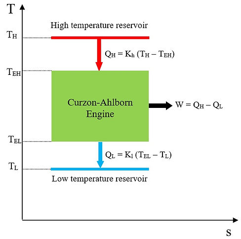
Fig.1 Engine model of Curzon-Ahlborn
Using Eq. (4), Eq. (1) reduces to

A combination of Eqs. (2), (3), (5) and (6) allows us to express Eq. (6), after some algebra, as
Differentiating Eq. (7) with respect to TEH and equating it to zero leads to an equation whose final solution gives
Substituting Eq. (8) into Eq. (5), we also find (TEL)opt = TL. The minimization of the entropy generation associated with Curzon-Ahlborn model suggests that any irreversibility between the thermal reservoirs and the engine should be removed, which will consequently lead to zero finite time power, and thereby zero efficiency. On the other hand, the work produced by the engine is
Using Eqs. (2), (3) and (5), it can be shown that
Applying ∂W/TEH = 0 leads to

The corresponding maximum work production of the engine is given by

It is known that the Curzon-Ahlborn engine efficiency at maximum work is ηC-A = 1 – √(TL/TH) [14]. Equation (12) corresponds to a maximum finite time work output. Therefore, we conclude that the regime of maximum work operation is different from the regime of minimum entropy generation for the model of Fig. 1.
To find out whether there is any relationship between the entropy production of the Curzon-Ahlborn and its thermal efficiency, we represent Eq. (7) in a dimensionless form by dividing it by Kl. Hence,
Using Eqs. (4) and (5), the thermal efficiency of the engine may be represented as follows.

We may also rewrite Eq. (10) in a normalized form as

where W* = W/(KlTL).
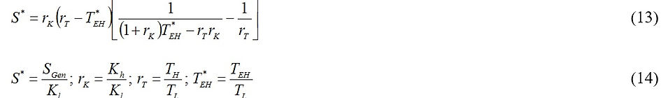
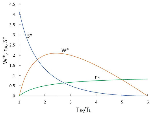
Figure 2 shows the variation of the thermal efficiency, normalized work output and normalized entropy production of the Curzon-Ahlborn engine with T*EH for typical values of rT = 6 and rK = 2. It can be seen that as the entropy production monotonically decreases by increasing T*EH, the thermal efficiency increases. On the other hand, the work output peaks at T*EH = 4.82. Note that as T*EH → rT, the thermal efficiency approaches ηC; i.e., the Carnot efficiency, and the entropy produced by the engine approaches zero. However, at this condition, the finite work output of the engine reaches zero. From this analysis, we conclude that for the Curzon-Ahlborn engine, minimization of the entropy production is equivalent to maximization of the thermal efficiency, but not to maximization of work production.
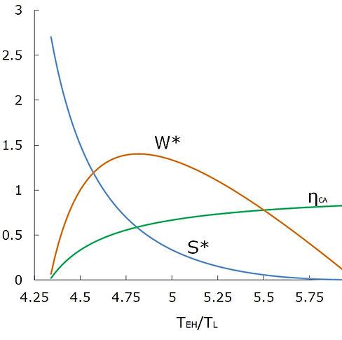
Fig.2 Variation of the thermal efficiency, normalized work output and normalized entropy production of the Curzon-Ahlborn engine with T*EH = TEH/TL (rT = 6, rK = 2)
Before closing this section, we note that the varying parameter in our thermodynamic optimization was T*EH, and it was assumed that rK is constant. One may argue that in some cases, we may treat T*EH as a fixed parameter and optimize the system by varying rK. This is also a possible situation; however, our conclusion mentioned in the previous paragraph still hold correct. In other words, even with varying rK and fixed values of T*EH and rT, it can be shown with a similar analysis presented previously that minimum entropy production correlates with only maximum thermal efficiency, not with maximum work output. This is graphically demonstrated in Fig. 3.
Fig.3 Variation of the thermal efficiency, normalized work output and normalized entropy production of the Curzon-Ahlborn engine with rK (rT = 6, T*EH = 5)
Novikov Engine
The engine model of Novikov is depicted on a T-s diagram in Fig. 4. Notice that in this model, the temperature at the cold-end side of the plant is the same as the low temperature reservoir temperature, TL. As the engine is internally reversible, its efficiency can be represented as

The work produced by the engine can be obtained from Eq. (18).

Substituting Eq. (2) into Eq. (18), we find

Assuming a constant Kh and fixed TH and TL, Eq. (19) has an optimal with respect to TEH. Because, at the extreme limit TEH = TL, W = 0, and at the other extreme limit TEH = TL, W = 0; implying that the work output of the engine possesses a maximum value at an optimum value of TEH between TL and TH. Differentiating W in Eq. (19) with respect to TEH and equating it to zero yields an equation whose solution for TEH gives

Substituting Eq. (20) into Eqs. (17) and (19) allows us to find the efficiency and the work output of the engine model of Novikov at maximum work operational regime.

Fig.4 Engine model of Novikov
An interesting observation is that the efficiencies of the heat engine models shown in Fig. 1 and Fig. 4 at maximum work output are the same. However, comparing Eqs. (22) and (12), one may notice that the maximum work produced by the Novikov’s engine is different from the maximum work generated by the Curzon-Ahlborn’s engine. It can be further realized that when the thermal conductance at the cold-end side of the engine in Curzon-Ahlborn’s model tends to infinity Kl→∞, the model of Curzon-Ahlborn reduces to the model of Novikov.
In the next step, we calculate the entropy generation associated with the operation of the Novikov’s model. There are two flows of heat: QH and QL. So, the total entropy generation can be found as follows.
Notice that the cold-end side temperature of the engine is the same as the low temperature thermal reservoir temperature. Inserting Eq. (2) into Eq. (23) yields

Solving ∂SGen/∂TEH = 0 leads to an optimum TEH giving a minimum entropy production.

Equation (25) reveals that the minimum entropy generation takes place when TEH → TH, which would give a zero finite time work. Therefore, we confirm that the operational regime of minimum entropy generation is different from that of maximum work production; a similar result which we obtained for the model of Curzon-Ahlborn.
Let us now consider a modified power plant model of Novikov, in which the finite time heat exchange only takes place at the clod-end side of the engine (see Fig. 5). Thus, the efficiency and the work output of the engine are given by Eq. (26) and (27), respectively.

Fig.5 Modified Novikov engine on a T-s diagram
Note that the subscript “MN” denotes modified Novikov. Substituting Eq. (3) into Eq. (27) and rearranging, we get

Similar to the work output of the Novikov’s model given in Eq. (19), there is an optimal for TEL between TL and TH which leads to a maximum work output. Thus, maximization of W in Eq. (28) with respect to TEL yields

The efficiency and the work output of the modified Novikov engine at maximum work production condition are obtained by substituting Eq. (29) into Eqs. (26) and (28).
Comparing Eqs. (31) and (12), it can be inferred that when the thermal conductance at the hot-end side of the Curzon-Ahlborn’s model tends to infinity Kh → ∞, the model of Curzon-Ahlborn reduces to the modified power plant model of Novikov.
To evaluate the production of entropy, we note that there is merely one source of entropy generation at the cold-end side of the engine due to the finite time heat exchange, while the heat transfer at the hot-end side of the engine takes place reversibly. Hence,

A substitution of Eq. (2) into Eq. (32) gives

To minimize entropy generation, we apply ∂SGen/∂TEL = 0 to find the corresponding optimum TEL. The result is

Substituting Eq. (34) into Eq. (28) leads to W = 0. Therefore, we conclude that the minimum entropy generation and maximum work output are two different operational regimes in the modified Novikov power plant model.
Similar to the case of Curzon-Ahlborn model, the relationship between the entropy production and the thermal efficiency is graphically demonstrated in Fig. 6 for the Novikov engine and the modified Novikov engine. In both cases, W* and S* denote the normalized work output and the normalized entropy production, respectively, as defined in previous section. Note that the results for the Novikov’s model are presented as a function of TEH/TL, whereas those for the modified Novikov model are versus TEL/TL.
(a)
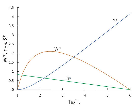
(b)
Fig.6 Variation of thermal efficiency, normalized work output and normalized entropy production of (a) Novikov’ engine, and (b) modified Novikov’s engine (rT = 6)
Figure 6 reveals that an increase in the entropy production is equivalent to a decrease in the thermal efficiency for both cases. For the case of Novikov’s engine, the thermal efficiency monotonically increases with TEH/TL and the entropy production consistently decreases with TEH/TL. The work output of the engine peaks at TEH/TL = 2.1. For the case of modified Novikov’s model, with an increase in TEL/TL, the thermal efficiency decreases and the entropy production increases. The work output attains its maximum at TEL/TL = 2.1. From this discussion, we arrive at the conclusion that for the power plant models of Novikov and modified Novikov, the minimization of the entropy production is equivalent to the maximization of the thermal efficiency, but not to the maximization of work production; a similar conclusion that we reached for the case of Curzon-Ahlborn model.
Carnot Vapor Cycle
A schematic of the Carnot vapor cycle is shown on a T-s diagram in Fig. 7. Unlike the heat engine models examined in previous sections, which are interacting with fixed temperature thermal reservoirs, the model of Fig. 7 exchanges heat with a hot stream whose specific heat is cp,h, and a cold stream with a specific heat of cp,l. The cycle undergoes an isothermal evaporation process at temperature TEH, and an isothermal condensation process at temperature TEL. The evaporation process takes place by receiving heat from the hot stream through a heat exchanger. The inlet and outlet temperatures of the hot stream are Th,in and Th,out (<Th,in), respectively. At the cold-end side of the engine, the condensation heat is rejected through another heat exchanger, to the cold stream which enters the heat exchanger at temperature Tl,in and exits at temperature Tl,out (>Tl,in).
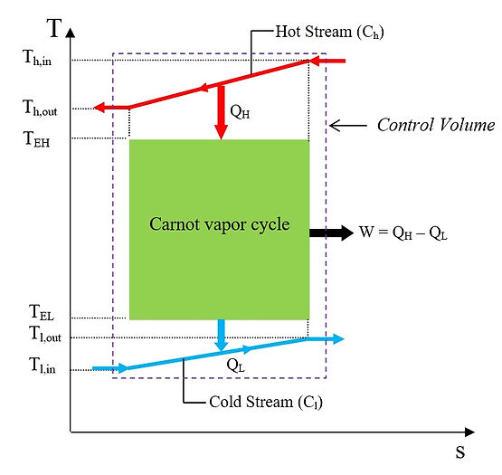
Fig.7 Schematic of a Carnot vapor cycle on a T-s diagram
Let us now assume that both heat exchangers at the hot-end and the cold-end sides are operating ideally with 100 percent effectiveness. In other words, the temperature of the hot stream leaving the hot-end side of the engine is equal to the evaporation temperature; i. e., Th,out = TEH, and the exit temperature of the cold stream is the same as the condensation temperature; i.e., Tl,out = TEL. In this case, the amount of heat supplied from the hot stream for evaporation of the working fluid is

The amount of condensation heat rejected by the engine at the cold-end side heat exchanger is absorbed by the cold stream; whose temperature rises from Tl,in to Tl,out. Hence,

As the power producing compartment is internally reversible, its efficiency obeys

The subscript “CV” in Eq. (37) denotes Carnot vapor cycle. A combination of Eqs. (35) – (37) allows us to establish a relationship between TEL and TEH.

By applying the first law, the work output of the power cycle is obtained as follows.

A substitution of Eq. (38) into Eq. (39) gives

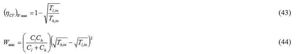
For given values of the hot and the cold streams inlet temperatures; i. e., Th,in and Tl,in, and fixed heat capacitances of hot and cold streams, the work produced by the power plant has only one degree of freedom, TEH. Maximization of the work with respect to TEH yields

Inserting Eq. (41) into Eq. (38), we get

The efficiency and the work output of the Carnot vapor cycle at the condition of maximum work production are obtained by substituting Eqs. (41) and (42) into Eqs. (37) and (39).
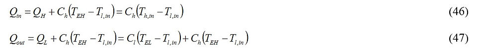
An important observation in the power plant model of Fig. 7 is that unlike the models of Figs. 1, 4 and 5 in which all amount of heat supplied from a thermal reservoir is transferred to the engine, here only some fraction of the energy denoted by QH (see Eq. (35)) is transferred to the power producing compartment. If the energy of the hot stream exhaust is directly dumped to the atmosphere characterized with temperature Tl,in (without any usage in the downstream of the power plant, thereby wasting some useful energy), the thermal efficiency of the entire plant is given by

where
A combination of Eqs. (44) – (46) leads to an expression for the thermal efficiency of the plant at maximum work operational condition.

We emphasize that Eq. (37) represents the efficiency of the power producing compartment only, while Eq. (45) gives a fraction of the total heat input converted to the desired form of energy; i. e., work. It is worth mentioning that the thermal efficiency given in Eq. (45) peaks at an optimum TEH. Because the heat input Qin is constant, the maximum thermal efficiency takes place at exactly the same optimum TEH that the work output becomes maxima; i.e., Eq. (41).
Next, we evaluate the entropy generation associated with the operation of the Carnot vapor power plant. Entropy is generated due to the heat transfer from the hot stream to the working vapor, and the heat transfer from the working vapor to the cold stream. Thus, for the configuration given in Fig. 7, we write
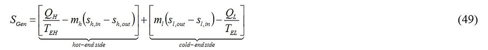
Taking into account Eq. (37), Eq. (49) reduces to

Equation (50) could also be obtained by applying an entropy balance for the control volume shown in Fig. 7. Neglecting any pressure drop in the flow path of the hot and the cold streams and assuming constant specific heat throughout the heat exchangers for both streams, Eq. (50) can be expressed using the relationship s = s0 + cpln(T) as
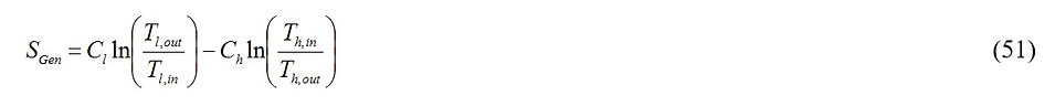
Based on the assumption that Th,out = TEH and Tl,out = TEL, Eq. (51) is rewritten as
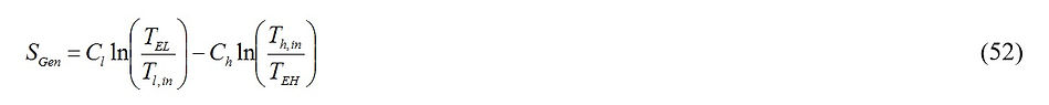
Substituting Eq. (38) into Eq. (52) yields

For fixed values of Cl, Ch, and Th,in, solving ∂SGen/∂TEH = 0 leads to the following result.

It can be seen that minimization of entropy generation leads to an optimum TEH which is different from the one obtained based on maximization of the work output; see Eq. (41); implying that the operational regimes of entropy generation and maximum work are not identical. A substitution of Eq. (54) into Eq. (38) results in TEL = Tl,in. So, the amount of heat exchange at both the hot-end and cold-end sides will be zero; leading to zero finite work output.
Summary
We examined typical simple power plant models including Curzon-Ahlborn, Novikov and modified Novikov models, and Carnot vapor cycle. The unique and common feature of these power plants is that the compression and the expansion processes take place isentropically. The key observation made is that the production of entropy is an indication of a reduction in the thermal efficiency of an endoreversible power plant. This is consistent with previous findings on ideal simple and regenerative Brayton cycles [10].